INTRODUTION AND CONFIGURATION TO UPPC® SYSTEM
UPPC® (Ultra Performance Plant Controller), also known as the “Ultra-Efficient Control System for Optimized Energy-Savings in Central Air-Conditioning Chiller Stations”, is a universally applicable control system designed to optimize energy use of chiller plants, including: primary water systems, secondary water systems, constant speed and variable speed chillers. The purpose of the UPPC® system is to maximize performance efficiency (or to minimize operating energy use) of a chiller plant as a whole. Based on the fundamental characteristics of each equipment group, the UPPC® coordinates all components of a chiller plant according to predefined optimization strategy to accurately match the system real-time cooling load.
The UPPC® Control System can improve the annual comprehensive efficiency of a plant from 0.9kW/ton to 0.6kW/ton with realizing 33% of energy-savings, when implemented in a full frequency chiller plant adopting variable-speed chillers. In the case of application to a chiller plant adopting constant-speed chillers, the annual comprehensive efficiency can be improved from 0.9kW/ton to 0.65~0.7kW/ton with an energy saving of 22% -27%.
The UPPC® “Central Air-Conditioning Chiller Plant Energy-Saving Control System” employs a mainframe computer and industrial programmable logic controllers (PLCs) as core hardware components, and the patented UPPC® energy-efficiency optimization algorithm as core software component. The system monitors with transducers and implements with VSD, thus providing a viable solution to control systems. The UPPC® Energy-Saving Control System tracks performance curves of chillers, chilled water pumps, condenser water pumps and cooling towers as well as system real-time load. In such manner, UPPC® performances proactive control over each individual device and conducts comprehensive optimization for the whole plant, in order for the minimal total energy consumption for the chiller plant comprehensively.
The UPPC® Control System has a two-tier architecture. The upper level hosts an industrial control computer as the mainframe console, responsible for implementing overall control strategies and maintaining surveillance over operating conditions of the entire plant. The lower level consists of industrial PLC (programmable logic control) devices that actually control the operation of all related equipment.
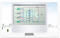
The Central Console
Basic hardware to the central console is an industrial control computer installed with the essential UPPC® Optimization Algorithm Software. This software uses equipment proxies or models, as groundwork for computation; then runs optimization algorithms with operating data collected from each equipment-control substation; finally, optimized results are transmitted back to each equipment-control substation for execution. In addition, the software interface of the central console provides management of the plant’s daily operation.
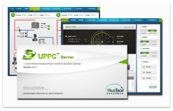
The UPPC® Energy Efficiency Optimization Software
The software core to the central console consists of optimization algorithm modules compiled from mathematical models and optimization programs. The main goals of the software are:
1) perform periodic collection of required transducer or sensor data from lower level PLCs;
2) input collected data to optimization algorithms and run calculations to derive the most logical, most energy-efficient set of results for use as control strategies for plant facilities, then to transmit strategy commands to the appropriate PLC so that each PLC may perform specific control over device operation.
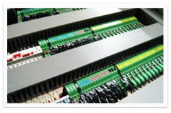
Facilities-Control Substations
Each UPPC® system is composed of a number of equipment-control substations. Each substation is based upon an industrial grade PLC (programmable logic controller) and executes command signals issued from the central console and from the PLC to effectively manage chillers, chilled water pumps, condenser water pumps, cooling towers, and relevant equipment. The substations also collect system-operating parameters from respective transducers and transmit data via industrial Ethernet to the central console for optimization program computation. Each equipment-control substation is connected to the InterBus communication module for correspondence.
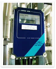
Sensors and Executive Devices:
Sensors (and transducers) and executive devices relevant to control systems often include:
- Chiller evaporator inlet isolation valve
- Chiller condenser inlet isolation valve
- Cooling tower inflow pipe isolation valve
- Cooling tower outflow pipe isolation valve
- Chilled water bypass pipe modulating valve
- Supply/return chilled water temperature transducer
- Supply/return cooling water temperature transducer
- Chilled water supply flow meter
- Cooling water supply flow meter
- Chilled water supply/return pipe differential pressure transducer
- 3-phase AC power transmitter
- Outdoor temperature and humidity transducer
VSD (Variable Frequency Drive) Controllers
For a centralized air-conditioning system, the volumes for chilled water pumps and condenser water pumps are selected according to the building’s maximum design load plus some margin. Due to seasonal changes, differences between daytime and nighttime weather conditions, and changes in end-user-specific load requirements, the actual air-conditioning load under the majority of circumstance falls below the design capacity. The default design differential temperature is generally 5~7°C for chilled water and 4~5°C for cooling water; when the water system maintains constant flow rate, run-time differential temperature is merely 1 ~ 3 °C for most of the year. This operating condition of low differential temperature and high flow rate brings waste in the power consumption of active water pumps. Using VFDs to regulate pump speed allows for convenient adjustment of water flow and save the pumping system’s energy use when operating at part load.